3D Scanning
An example of the 3D Spatial Scanning Process
To get started, hover over the slides and use the Left/Right arrow buttons to navigate among them:
-
Catwalk Example
In this example, we scanned two catwalks, each approximately 41'-0" high and 78'-0" long to design stiffeners to make each catwalk safe to walk on.
-
Step 1 Scanner Setup
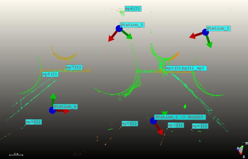
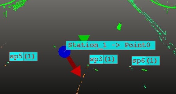
Set Control. As seen below, 4 scanner positions (Noted Station _1 etc) were used to obtain the point cloud required to model an accurate catwalk. The "SP's" indicate spheres that were used as common control points. After station 1 was set up, common spheres where used to "Back Sight" to create common control between each station.
-
Step 2 Scan Area
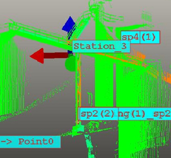
Scan Area. This image shows the partial point cloud created by the scanner of the existing condition of both catwalks. All four stations were from the ground at a distance of approximately 100'-0" from the catwalks. The scanner allows the user to collect very accurate data from a safe distance.
-
Step 3 Produce 3D Solid Model From Point Cloud
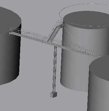
3D Modeling. Once the points are collected in the field, another program is used to create 3D solid objects of all the data collected in the field. The image below is the product of modeling from the point cloud. Note: It is 100% up to the client on what to model or not to model. Not all points have to be modeled and can be stored to model at a later date.
-
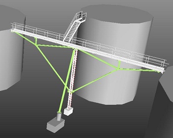
Step 4 Engineering and Design
3D Steel Design. In this exercise, the deliverables were to engineer and design structural stiffeners with 2D Plan and section drawings for installation. The image depicts the 3D structural engineering and design.
-
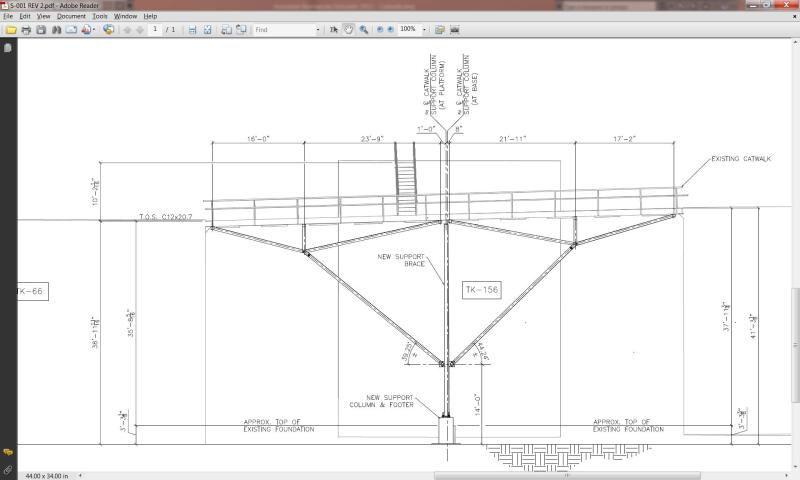
Step 5 Final Deliverables
Once engineering and design are complete, 2D plan and section drawings are created from the 3D model for estimating and construction.


